Table of Contents
Diesel Generator Major Maintenance
Maintaining a diesel generator on a boat is a big job. It’s like the vessel’s heart, ensuring all the important electrical stuff works well, from GPS systems to lights. Diesel generators give the power that makes boats go, and it’s super important they work reliably for safety and efficiency.
We will discuss “Major Maintenance for Diesel Generators on Boats” in this blog. Our main focus will be on the Ship’s Engine components like Cylinder heads, Liners, and pistons.
We wish to provide you with practical information based on our practical experience maintaining and overhauling the Ship’s generators and machines. The information will be less theoretical and concentrate more on procedures in practice to maintain the modern-day Generators. Many books are written on this subject, but most are more theoretical and don’t provide complete information about the maintenance and the practical difficulties faced by Marine Engineers on board ships.
So, prepare as we set sail to understand the importance of keeping your diesel generator in top shape, paying special attention to these engine parts for boats out in the open sea. Your boat’s reliability and your peace of mind are on the horizon!
Key Tests for Diesel Generator Major Maintenance
To do important and complicated jobs like overhauling a ship’s generator, you need to know all about the engine parts, what they do, and the steps and tests needed for the repair.. As the lifeline of ships, generators require regular maintenance, including regular and major overhauls. As a Marine Engineer, you must be competent enough to overhaul Generators during maintenance. A thorough knowledge of the Diesel Generator Overhauling process is therefore essential for any level of marine engineering. Various tests are performed on various tools and parts of the generator before and during the overhaul. Below are ten important tests performed during a ship generator overhaul.
Bearing cap serration test
Bearing cap serration testing is an essential part of a diesel generator overhaul. This test is carried out to ensure that the serrations on the bearing housing hold both caps tightly with the connecting rod bolts. The. This test helps reduce damage from excessive vibration during operation.
The serration test includes a detailed visual inspection of all bearing caps and related parts. Engineers look for signs of wear and tear that can affect generator performance. If defective parts are identified, replace them immediately to extend service life. By performing this test regularly during general overhaul, the diesel generator can be operated safely and reliably for an extended period.
Hydraulic jack test
Hydraulic jacks are essential for various tasks when overhauling diesel generator sets. These tools will help you open the main engine cover cylinder head, bottom bolts, and other components such as fuel pumps, valves, etc. Testing these hydraulic jacks is essential because these jobs require immense strength and precision before use. A hydraulic jack test ensures all generator components are installed and functioning correctly before servicing. In this way, you will ensure the satisfactory operation of your generator throughout its lifetime.
Cylinder head Hydro
The cylinder head is a significant component of any diesel generator set. A cylinder head overhaul is essential to a major overhaul as it must be checked and tested regularly to ensure safety and efficiency. Ensure this requires the cylinder head to be overhauled and reused on board or even overhauled when new cylinder heads are delivered from shore.
The process of testing these cylinder heads is complicated but necessary. All components, including valves, valve springs, valve guides, gaskets, and other parts, should be thoroughly inspected before reuse or overhaul. This process is critical for the proper and maximum efficiency of diesel generators.
Connecting-Rod bolts test
The diesel generator under the cap contains the connecting rod bearing and is bolted to the bottom end. These bolts are exposed to high alternating loads during operation. Hence it is important to test these bolts frequently at the species maintenance hours to ensure their good shape and worthiness to sustain the stress and forces.
One of the most important tests for this is the connecting rod pin test. Monitoring of connecting rod bolts for signs of wear and tear will be examined with this test. This test identifies potential problems before they cause severe damage to the engine or other parts of the diesel generator set.
Connecting Rod Bend Test
Connecting rods are under extreme pressure. When overhauling an alternator, check the straightness of the connecting rod by inserting a brass rod into an oil hole slightly smaller in diameter than the oil hole of the connecting rod. If the connecting rod is bent somewhat (not visible to the naked eye), the brass rod will not fit into the hole.
Fuel Valve Test
Proper tools and skills are needed for major jobs like overhauling a Diesel generator. The role of a file injector is to supply the fuel to the combustion chamber of an engine at the correct pressure, timing, and in mist, form to make the homogeneous mixture for the complete combustion fuel and efficient running of a generator. Therefore, it is necessary to ensure that these fuel injectors are in proper working condition before reuse after overhaul.
Test of an injector is the most critical job during the overhaul process. This test ensures that the injector’s internal components -Nozzle, needle, and valve are functioning correctly and efficiently. The timely application of this test can extend the life of the diesel generator set.
Starting air valve testing
The air start valve is overhauled and reused, as are the fuel injectors. To check its correct functioning, all starting air valves are tested for leaks with starting air before installation in the cylinder head.
Relief valve test
Cylinder head relief valves are pressure tested to ensure proper operation. It is an important part that prevents head explosion and combustion chamber damage due to overpressure. Pressure testing is performed on a bench-mounted test stand consisting of high-pressure air, a pressure control valve, and a calibrated pressure gauge. Screw the relief valve onto the accumulator flange and increase air pressure until the valve rises. The settings are made accordingly.
The current test
This test is an important test performed after completing the major overhaul procedure and before testing the generator with fuel. When the Engine is ready, the turning gear is activated, and the Engine rotates with the indicator tap open. The current is monitored continuously. A fluctuating or increasing current value indicates a blockage or problem with the rotating shaft.
Alarm and Safety Trip test
Generator alarms and safety trips are electrical systems with wiring and contacts. All prime mover alarms and shutdowns are tested to verify their correct operation, including lube shutdowns, high coolant temperature shutdowns, and Overspeed shutdowns,
Note:- For the proper maintenance of Diesel generators, Engineers should understand the following.
- knowledge of design, construction
- Working of the machine.
- Overhauling Procedure and Maintenance works: There are standard procedures for the Diesel Generator Overhauling Procedure and maintenance of these machines, irrespective of their design and manufacturing.
Major Overhauling/De-carbonisation:
The process of dismantling, cleaning, and removing carbon deposits from the following parts.
- Piston
- Cylinder Liner
- Cylinder head
When Major Maintenance/Decarbonization is Needed
- Completion of running hours as per the planned maintenance program of OEM (Original equipment manufacturer).
- Accident/Breakdown.
- Before continuous surveys in which process of change of running parts like piston rings etc.
There are standard procedures for maintaining these machines, irrespective of their design and manufacturing.
Key Considerations for Maintenance Planning
- Makeshift arrangements for the emergency in the event of a Power failure
- Special Tools and tackles to be in proper operating condition.
- Measuring Instruments and Tools: All measuring tools, gauging, and measuring devices should be in suitable working conditions with a reasonable calibration period.
- Spare Parts: Check and ensure the availability of spares needed for maintenance.
- To ensure the working of Power Packs if available on board.
- Engineers/technicians involved in the care should know the procedure per the Operating manual.
- The maintenance team should have Knowledge of symbols and signs used to indicate the safety of machinery.
Real Life Incidences
- Onboard, the engineer in charge did not take a ship inventory of the spares. While the maintenance was on the way, during the inspection, it came to the light that the Con-rod bolts were elongated and needed replacement. The overhauling period was extended since the bolts were unavailable in the ship’s stock. Due to this delay, the company has to lose revenue for not taking the container with perishable goods because of lack of power.
- Before the hydraulic tool’s maintenance pump for loosening the Cylinder head, the Main Bearing and Con-rod nuts were not building pressure. During the maintenance, the engineer –in charge found out that the nuts were not getting loosened up, and hence dismantling work couldn’t be started. Ultimately it caused a delay in maintenance.
- Very often, it has been observed that due to the proper upkeep and maintenance of Measuring instruments/ calibration of the same in the stipulated period, many instruments fail to operate or lead to inaccurate measurements.
Getting Ready for an Overhaul
Essential Preparations Before Maintenance
- Quarantine
- Tagging Out
- Inspection of special tools supplied by the Manufacturer.
- Knowledge of functioning and procedure for operating the devices.
- Referring to the correct tightening torque and hydraulic pressure values.
- Complete understanding of parts assembly.
- Preparation of safety regulations for safe working.
Before maintenance begins, it’s crucial to quarantine the machine to prevent spills and accidents. This includes isolating both the prime mover and alternator for safety.
Steps to Isolate Electrical and Mechanical Systems
- Open the ACB ( Air Circuit Breaker) to cut off the alternate and bus bar links.
- The power supply of the Pre-Lube Oil Pump.
- Oil supply to Engine
- Cooling water supply
- Lube oil
- Fuel oil supply
- Air supply
A checklist of all the isolated areas is to be prepared, and the same is to be referred to before reopening the systems.
During the isolating process/opening procedure, a slow action with close observation must be followed to ensure other equipment is not affected.
Add on safety: While the maintenance work is in progress, additional tagging is to be carried out to prevent any opening up of Valves or Electrical breakers resulting in an accident of a serious nature.
Checking Engine Manufacturer’s Special Tools
- Injector and starting valve opening tool
- Spanners
- Cylinder head opening tool
- Cylinder Liner Removal Tools
- Cylinder Liner Holding Tool
- Cylinder head lifting tool
- Piston Lifting tool
- Bearing removal tool
- Cylinder Head and con rod nuts loosening and tightening hydraulic tool
- Valve grinding tool
- Valve seat grinding machine/tool
- Injector testing tool
- Rope and ceilings with proper size D shackles.
- Overhead cranes.
- Engine Barring arrangements
- Cylinder Liner Brushing tool
- Piston Ring removal tool
- Piston guide tool for inserting the piston.
- All the pressure and temperature calibration instruments.
- Electrical measuring instruments.
Assembly Guidelines to Follow
- The engineer in charge should know the assembly of parts and doubt the Instruction manual/Consult with the Senior Engineer.
- Store all the dismantled components in a separate box with the marking on significant parts. For each unit, a separate container is to be used.
- Mark all the bearings and con-rod bolts and wrap the threads with the cloth to avoid the threads’ damage.
Perform the Following Tasks
Cylinder Head Maintenance Checklist:
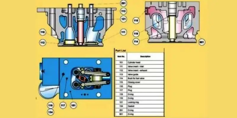


- Decarbonize all cylinder heads.
- Inspect cylinder heads for wear or damage.
- Examine valve spindles for proper functioning.
- Inspect Inlet and Exhaust valves, as well as Inlet valve guides, and record measurements.
- Replace corroded or worn-out valve guides with new ones.
- Inspect valve seats, rejecting excessively damaged ones and re-grinding accepted seats.
- Disassemble valve rotators for inspection, looking for deep markings on ball pocket surfaces.
- Inspect all Injector Sleeves and document observations.
- Verify and adjust safety valve operating pressure.
- Examine Indicator valves.
- Check cylinder head cooling water spaces.
- Lap cylinder head seating faces.
- Perform pressure testing on all cylinder heads.
- Conduct valve seat grinding for both old and new seats.
- Remove, clean, inspect, and reinstall Water guide jackets with new O rings.
- Properly tighten cylinder head nuts following OEM torque specifications.
Ensure thorough maintenance for optimal performance.
Cylinder Liner Maintenance Procedure:
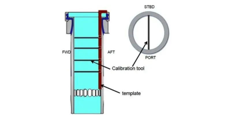


- Remove all cylinder liners for inspection.
- Conduct inspection, bore measurement, and honing at the workshop following OEM guidelines for Cylinder Liner Inspection and Honing.
- Record size measurements in the provided forms.
- Perform lapping on the upper face of the cylinder liner.
- Replace all flame rings with excessively worn-out working surfaces.
Follow these steps to ensure proper cylinder liner maintenance.
Piston Inspection and Overhauling Procedure
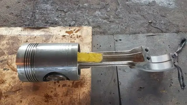


- Remove all pistons for inspection and overhaul.
- Perform decarbonization on all pistons, ensuring thorough cleaning both inside and outside.
- Clean all piston and oil scraper ring grooves, then inspect and measure them for wear using the groove measuring tool provided by the OEM. Record the measurements.
- Replace all piston rings with new ones.
- Ensure that the piston ring positions are offset 180 degrees from each other, and the spring joint of the scraper ring is also fitted with a 180-degree offset to the joint during piston installation.
- Verify the tightness of the piston plug at the specified torque.
Follow these steps for proper piston maintenance and overhaul.
Central Tools 6434 Sleeve Height and Counter Bore Gauge


Quickly measures the cylinder sleeve height using pointed contact; Counter-bore depth using flat end contact; Top dead center; Piston-to-deck height; Valve protrusion; Easy readings around the entire bore. This is a compact and very versatile gauge.
Connecting Rod Inspection Steps
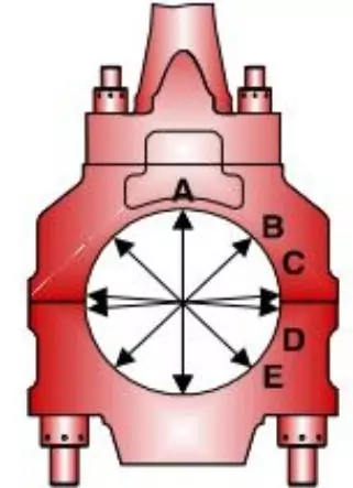


- Inspect all connecting rod big-end bearing shells. Replace any with deep grooves or excessive wear beyond accepted norms for shell thickness and free spread.
- Examine the connecting rod’s big end bore and document measurements.
- Check the small end bearings.
- Verify the clearance between the wrist pin and bush.
- Conduct an ultrasonic test on all piston pins to detect hairline cracks.
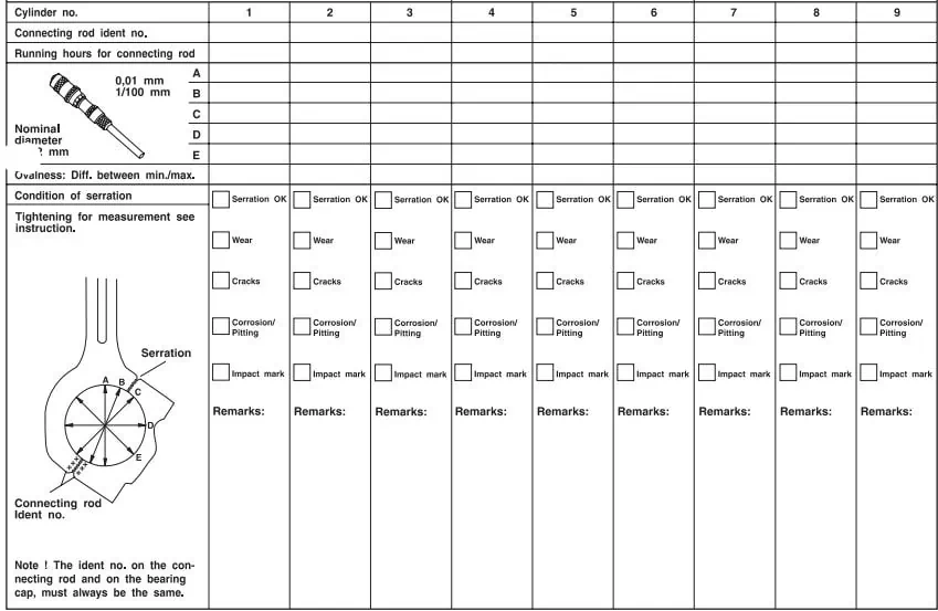


Follow these steps to inspect connecting rods to ensure proper maintenance thoroughly.
Connecting Rods Industrial Tools


Gear Wheel and Camshaft Inspection:
- Inspect all gear wheel bolts and connections following OEM instructions.
- Replace all camshaft bushes if worn out.
- Check the condition of the camshaft.
- Examine the lubrication of the camshaft, observing the flow of lube oil from all bearings and spray pipe nozzles. Ensure the oil jet hits the gear wheel precisely at the meshing point.
- Verify the tightness of locking devices and fasteners.
- Inspect all pushrods for straightness.
- Adjust inlet and exhaust valve clearances according to OEM recommendations.
Perform these checks to maintain the gear wheels’ and camshaft’s integrity and functionality.
Valve and Fuel Pump Mechanism Inspection
- Examine the Roller Guide for any marks.
- Check for deformation on the spherical stud.
- Inspect the surface of rollers for any marks or deformation.
- Verify the absence of free play between the rollers, the bush, and the pin.
- Inspect the Valve Gear, springs, and Pushrods.
- Examine all valve bridge springs, rocker arm brackets, and pushrods.
- Also, inspect the Roller Guide for fuel injection pumps.
- Ensure all roller guides are free of marks.
- Check the surface of rollers for defects and deformation.
- Confirm there is no free play between rollers, bush, and pin.
- Lastly, check the lubrication of all operating gears.
These inspections ensure the proper functioning of the inlet and exhaust valve mechanisms and fuel injection pumps.
Governor
- Overhaul the Governor.
- Change the Governor’s oil.
Crankshaft and Main Bearings Maintenance:
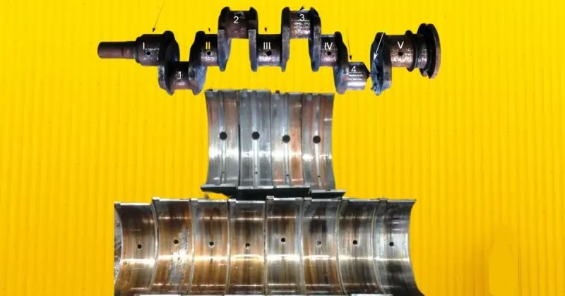


- Inspect all crankpins and polish all main and connecting rod pins with glossy paper.
- Examine thrust bearings and replace them if wear exceeds prescribed limits.
- Re-tighten counterweights to the specified torque.
- Disassemble all main bearings and polish all crankpins.
- Check for runout.
- Tighten the main and guide bearing caps to the prescribed torque.
- Inspect and replace any main bearings with abnormal wear.
Follow these steps for proper maintenance of the crankshaft and main bearings.
Turbocharger and Charge Air Cooler Maintenance:
- Remove the Turbocharger (TC) cartridge.
- Replace the nozzle ring.
- Dismantle the cartridge, inspect the bush and labyrinth ring, and replace if necessary.
- Re-assemble the cartridge.
- Check clearances following the procedure.
- Clean the Charge Air Cooler (CAC).
- Perform a pressure test on the Charge Air Cooler.
These steps ensure proper maintenance of the turbocharger and charge air cooler.
Engine Frame and Bed Plate Maintenance:
- Re-tighten the holding-down bolts.
- Re-tighten the bolts connecting the engine and base frame.
- Conduct a functional test of the safety cover.
- Inspect the AVM pad adjust screw clearance, and make adjustments if necessary.
These steps ensure the proper maintenance of the engine frame and bed plate.
Fuel Oil System Maintenance:
- Calibrate the fuel injection valves.
- Inspect all high-pressure fuel pipes and replace “O” rings.
- Examine the FIP roller and measure nominal height.
- Perform an overhaul of all fuel injection pumps, replacing the barrel, plunger, and ‘O’ ring kit as needed.
These steps are essential for the proper maintenance of the fuel oil system.
Lube Oil System Maintenance:
- Remove the engine-driven lube oil pump for inspection.
- Dismantle the entire pump and replace the bushes.
- Apply the correct torque to tighten the self-locking nut.
- Drain old oil from the engine and refill with new oil.
- Overhaul the pre-lube oil pump.
- Replace the lube oil filter cartridge.
- Clean and replace the Glacier bypass filter kit.
- Perform a chemical circulation cleaning of the lube oil Plate Heat Exchanger (PHE).
These steps are crucial for maintaining the lube oil system.
Water Pump and Thermostatic Valve Maintenance:
- Remove the LT (Low Temperature) and HT (High Temperature) water pumps from the engine.
- Perform a comprehensive overhaul of the pumps.
- Replace the rotating sealing and both ball bearings of the HT Water Pump.
- Replace the rotating sealing and both ball bearings of the LT Water Pump.
- Tighten the self-locking nuts of both pumps to the specified torque.
- Overhaul the HT water thermostatic valve.
- Clean the LT/HT Plate Heat Exchanger (PHE).
These steps are essential for maintaining the water pumps and thermostatic valve in optimal condition.
Mechanical Overspeed Device Maintenance:
- Perform an overhaul of the mechanical overspeed device.
This step ensures the proper maintenance of the mechanical overspeed safety mechanism.
Miscellaneous Procedures:
These are crucial steps in the Diesel Generator Overhauling Procedure:
- Record the Fuel pump index at Governor Index 0.
- Verify the integrity of the compressed air system.
- Inspect the fuel oil system and nozzle cooling system.
- Perform functional tests on safety shutdown switches and analog switches.
- Calibrate all safety switches.
- Consider replacing the alternator bearing if necessary.
- After completing maintenance, initiate the D.G. Set and follow the sequence for all moving parts per the standard Diesel Generator Overhauling Procedure.
- Conduct load trials of the D.G. Set according to the OEM protocol.
- Record the set’s performance during stage load sequences, ranging from 25% to the maximum available load, as specified in the manual.
- Continuously monitor parameters and log them in the logbook for reference.
These steps ensure a comprehensive and successful Diesel Generator Overhauling Procedure.
The thumb rule for oil clearance calculations
The reasonable starting point is 0.01905mm to 0.0254 mm. (Three quarters to 0.0254 of a millimeter) of clearance per mm of a shaft diameter.
For example, a 2 mm shaft diameter would require 0.0381mm to 0.0508mm (0.01905×2=0381 and 0.0254×2=0.0508mm)
For the super performance, engines add 0.0127 to the maximum calculated value. The recommendations for 2 mm shaft will be 0.0508 mm + 0.0127=0.0635mm.
(To maintain hydrodynamic lubrication between the shaft and bearing, the maximum ovality should not exceed the maximum oil clearance. If exceeded, there will be bearing failure due to boundary lubrication.)
